|
BRUCE ROBERTS CUSTOM YACHTS
|
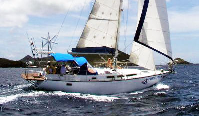
CRUISING SAILBOATS |
 POWER BOAT PLANS |
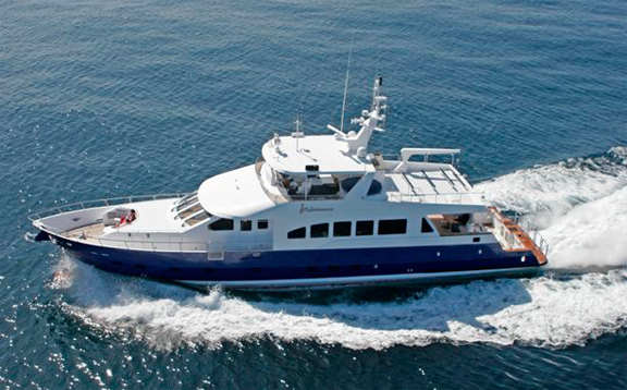
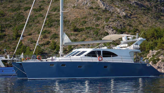
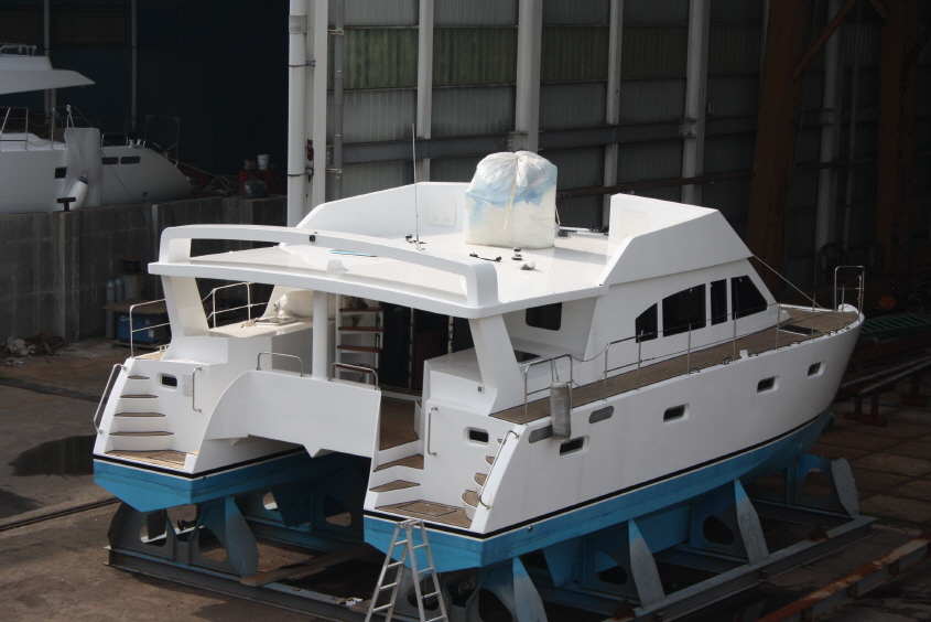
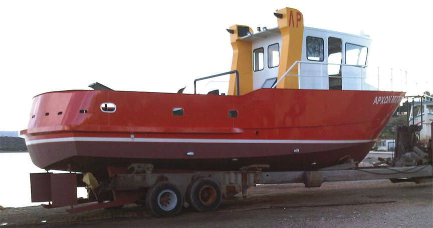
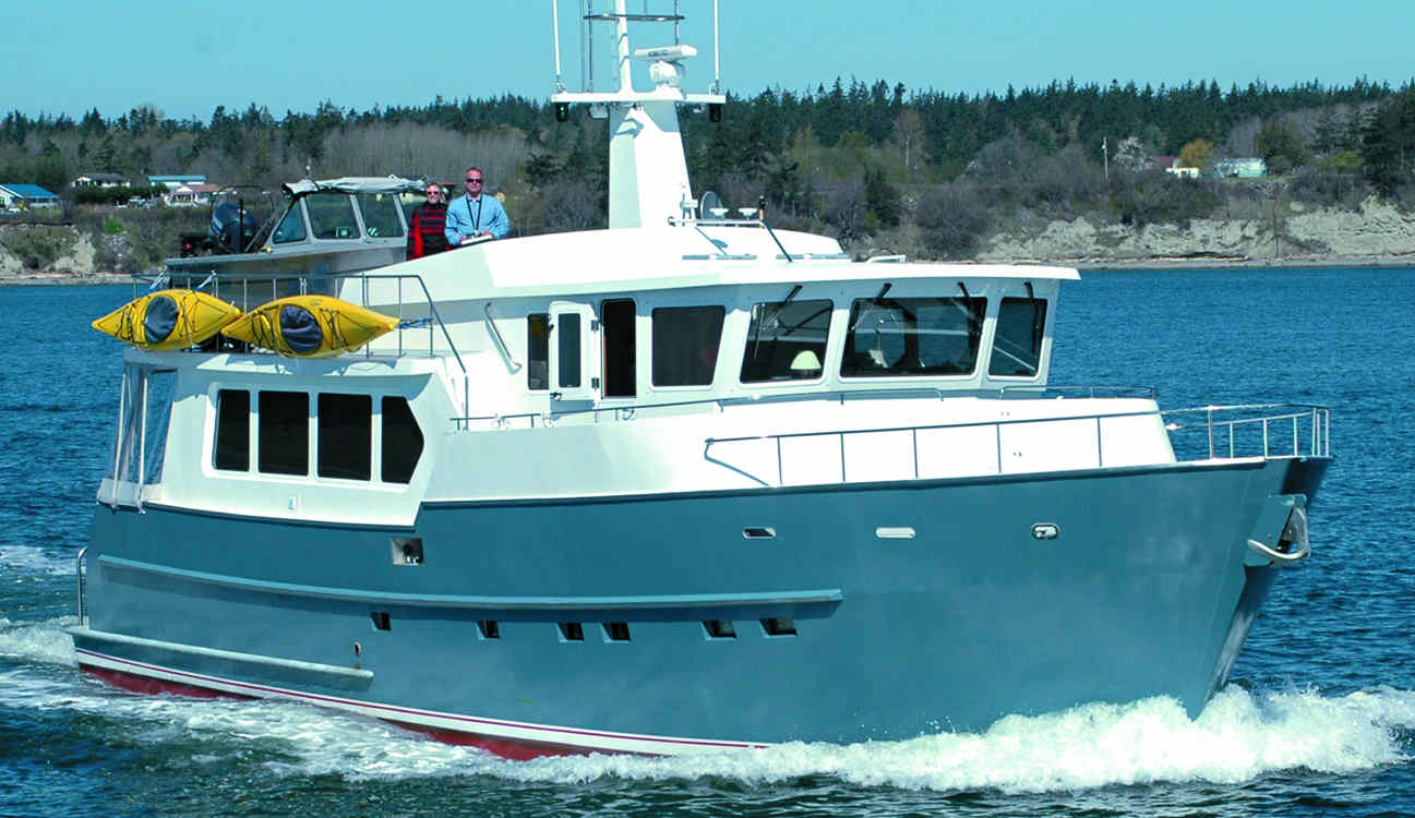 PASSAGE-MAKING TRAWLERS 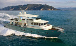 |
![Bruce[2].jpg (4158 bytes)](images/Bruce[2].jpg)
|
POWER BOAT KITS & CUTTING FILES What are CUTTING FILES & ASSEMBLY? ( SEE ASSEMBLY PAGE )
We offer "Cutting
files and boat plans" for our STEEL OR ALUMINUM PLANS & CUTTING FILES boats. What does this mean ? BRUCE ROBERTS CUTTING FILES AND PLANS FOR STEEL OR ALUMINUM PLANS & CUTTING FILES CONTAIN:
ASSEMBLY DRAWINGS: Each set of cutting files comes complete with 15 – 20 sheets of detailed assembly drawings with written instructions and check measurements (Both Metric and Imperial measurements are included) for assembling each part of the STEEL OR ALUMINUM PLANS & CUTTING FILES. The drawings cover assembling the frames, setting up the building jig (included in cutting files) on to I beams or similar base. These extensive and complete drawings take you right through the welding up process and completing the vessel from start to finish. ENGINEERING DRAWINGS: Also are included several sheets of detailed engineering drawings that cover the installation of the main engine(s), take home engine (if required), generating set, exhaust systems, fuel systems, fuel and water thanks etc. When you use our cutting files ... All plate parts belonging to the hull, deck and superstructure that will be accurately cut to size are included in the cutting files. The programming includes that the parts are marked with the appropriate part number and engraved matching marking lines to assist in the assembly and location of the part in its position. We recommend .... Cutting method of Plasma / Oxygen, ensuring highest accuracy and smooth edges, we also recommend that the plate parts are cut from Lloyds approved A Grade Shipbuilding quality ALUMINUM (as appropriate for aluminum designs) or STEEL (As appropriate for steel designs) that has been coated with factory applied Sigma weld MC welding primer. We also recommend that the steel plate has the official designation ISO standard 10474 or EN 10204 with 3.1.B certificate. If you cut locally we recommend that you use A36 / ABS GRA is the preferred steel quality which is equivalent to the ST37 Grade-A if above steel not available. The cutting files lists include all framing, stringers, engine beds, 'T' sole bearers, deck beams, deck stringers, all exterior plating, plus 3 main bulkheads & stiffeners are included. In the case of radius-chine hulls, the programming is included so that the radius plates can be rolled to the perfect shape and NO fitting is required. We recommend that you order all the profiles belonging to the hull; deck and superstructure as per the lists included and that these are supplied in sufficient quantity usually in factory lengths of 6 M / 20 ft, and in the case of steel profiles that these be coated with factory applied Sigma weld MC welding primer. Openings for windows and doors can be cut or only marked as per the builders preference. The main bulkheads are included in the cutting files and the drawings are included in the plans showing the stiffeners and are in accordance with classification rules and safety regulations. Details of the cold forming of plate parts are included where this requirement forms part of the design. Basic engine foundations are integrated into the cutting parts and assembly details. Included in the cutting files is a Setting up jig that incorporates the correct shape of the hull plates. The jig can be used as building jig for the entire hull after reinforcement plus there is an extensive building manual including detailed drawings, parts list and welding instructions. In these days where both the local authorities and the including better informed builders, it is important that the construction calculations are in accordance with prevailing classification society so this factor is part of the preparation of any Bruce Roberts set of cutting files. We can quote all of the other items you may require us to supply with the STEEL OR ALUMINUM PLANS & CUTTING FILES. We hope to hear from you again soon, EMAIL
FROM CUTTING FILE CUSTOMER: |
|
OPTION 1. Cutting files, assembly drawings, engineering boat plans. This option allows you to have the STEEL OR ALUMINUM PLANS & CUTTING FILES cut locally and this may be less expensive than a STEEL OR ALUMINUM PLANS & CUTTING FILES delivered from ourselves. Your location & other factors such the ability of the local cutting shop to undertake the bending and forming of parts that are part of the STEEL OR ALUMINUM PLANS & CUTTING FILES will have a bearing on your decision if a cutting files or option 2 ( STEEL OR ALUMINUM PLANS & CUTTING FILES ) are best for you….See CUTTING FILES EXPLAINED BELOW OPTION 2. Pre-cut STEEL OR ALUMINUM PLANS & CUTTING FILES delivered to your location. All the STEEL OR ALUMINUM PLANS & CUTTING FILES parts a perfectly cut and marked. All the formed and bent parts will have a perfect fit and we guarantee the STEEL OR ALUMINUM PLANS & CUTTING FILES to be complete and perfect in every way…. See STEEL OR ALUMINUM PLANS & CUTTING FILES ASSEMBLY EXPLAINED |
|
|
See left ... This is a set of parts cut and laid out as
they will be assembled into your hull deck and superstructure.
|
|
|
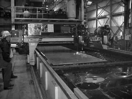
This is the type of machine your local cutting shop will use to cut out your STEEL OR ALUMINUM PLANS & CUTTING FILES. |
CUTTING FILES CAN BE NESTED TO A VARIETY OF SHEET SIZES.
Regards sheet sizes used to nest the
cutting files. We are prepared to re-nest the parts on to smaller or larger or
different size plates but the following should be kept in mind.
If the STEEL OR ALUMINUM PLANS & CUTTING FILES is cut from plates that
are too small; A width of say 1200 mm / 4 ft is considered too narrow and
for best results the plates should be at least 1.8 m / 6ft wide. Due to the
enormous amount of extra welding involved, the chances of having a perfectly
fair hull deck and superstructure will be greatly reduced if your STEEL OR ALUMINUM PLANS & CUTTING FILES is cut
from narrow plates. The larger the sheet sizes used to cut the STEEL OR ALUMINUM PLANS & CUTTING FILES ... the
smaller number of hull and deck plates ... the fairer the hull.
We have cut over 200 STEEL OR ALUMINUM PLANS & CUTTING FILES for sail and power boats ranging in size from 34 ft / 10.4 m to 85 ft / 26 m and in all cases the resulting plates avoided excessive welding and were easily handled using the minimum equipment.
In our cutting shops we use 6000 mm x
2000 / 19 ft 6 in x 6 ft - 6 in size sheets and occasionally 8000 mm x 2000 mm
/ 26 ft 3 ins x 6 ft - 6 in sized plate. We can of course re-nest these parts
to shorter plates ( more cutting and welding ) but we feel that the width of
the plates is even more important ... any plate under 2000 mm / 6 ft - 6 in in
width will mean some hull plates have to be cut lengthwise; not recommended
because of excessive welding which will adversely effect the final appearance
of the hull.
If the larger plates cost more then the
extra expense is justified when considering the reasons outlined above.
If in doubt, let us know what plate
sizes are available locally, try more than one supplier for quotes and most
importantly, DO try and obtain pre-shot blasted and primed plates and
profiles.
Finally make sure you get competitive
quotations for both Bruce Roberts and more than one local cutting shop. The
local cutting shop may need 'cutting and marking lengths' as this governs the
cutting machine times for cutting a particular STEEL OR ALUMINUM PLANS & CUTTING FILES, Bruce Roberts can supply
this information.
HOWEVER: When we supply the
Cutting files or the STEEL OR ALUMINUM PLANS & CUTTING FILES Study boat plans on DOWNLOAD or on USB Memory Stick. - YOU CHOOSE DOWNLOAD OR USB The Various calculations are on XL files so you would need access to MS-XL to read these files or if necessary you have prints made by ourselves or your local print center. SHEET 1AA ….Accommodation profile and accommodation plan with notes on arrangements. SHEET 1BB ….Alternative accommodation plan with Accommodation profile and accommodation plan with notes on arrangements. SHEET 1AAAA….Detailed accommodation plan in both plan and profile with measurements for the interior joinery etc. SHEET 3….Engine installation details including installation of fuel tanks, all shown in plan, profile and sectional view. Many explanatory notes included on this sheet. SHEET 5…. Details of chain plate construction, sizes, hole sizes for attaching correct size rigging screws, and instructions for cutting to correct dimensions etc. Suggested method of installing chain plates. SHEET 2A 02 (3) Shows each frame separately with measurements and layout of the numbered parts that go towards assembling each frame. SHEET 2A 02 (6) Complete welding schedule for all parts of the boat. Each weld is shown in graphic form so all can understand the exact weld required. 1 set of STEEL OR ALUMINUM PLANS & CUTTING FILES assembly photographs (.jpg) format Cut parts list with numbers
Sheet 12.
Electrical schematics. The STUDY boat plans show most of the above sheets of drawings but do not include cutting files!
The main steps in
preparing a new design for a boat that is destined to be cut out by a computerized
plasma-oxygen cutter is as follows. Firstly it is usually the customer who gets the
process started by contacting the designer with a brief outline of what they have in mind.
Further correspondence quickly establishes the clients ‘wish list’. The list
usually includes things such as type and style of boat, intended usage, overall length and
beam. Draft limitations should be specified at this stage.
Accommodation
requirements, number of regular crew as opposed to occasional guests should be stated.
Speed requirements are important as are the clients attitude to fuel costs. This list may
need some refining as some elements may conflict one with the other. It is part of the
designers brief to ensure that the client ends up with a boat that meets most if not all
their desires and overall requirements.
So far the process is
very similar to what would be followed no matter from which material or building method
was to be used to construct the vessel.
The next step is that
the client and designer enter into a (in our own case) simple agreement where the designer
agrees to prepare preliminary boat plans for the proposed vessel for a reasonable (a relative
term!) fee. In our office we consider that the lines plan, general arrangement drawings
consisting of exterior profile, deck plan, accommodation profile and plan views plus
sufficient calculations to ensure that the final design can meet the clients requirements,
constitutes a ‘Preliminary plan’.
Before a preliminary
plan can be produced it is necessary to produce a 3D computer generated model of at least
the hull of the vessel. Once the preliminary boat plans are completed and both the designer and
the client are satisfied with the overall concept and layout of the vessel then we can
proceed to preparing the complete boat plans for the vessel.
For the design to move forward it is
now necessary to complete the 3D computer model that would at this stage need to
include all items such as hull including transom, keel and rudder, all decks,
cockpits, complete superstructure, main interior bulkheads and any other
features such as Flybridge, radar arch, exhaust stack. Special items such as
transom steps and other similar features are all included in this model.
Depending on
the complexity of the design, this process can take between 500 and 600 design man hours.
From this model all of
the salient hydrostatics such as detailed weight calculations to enable material
requirements and final displacement to be calculated. This allows stability calculations
to be made at this time. During this process fine-tuning of the model can be undertaken to
make sure that the finished vessel will meet all the design requirements.
Once the 3D model is
completed and checked, then copies of this model are provided to the specialized designers
who prepare the final model that includes all the scantlings such as transverse and
longditunal framing, sole bearers, deck beams and engine beds. This same team then
separate out all the parts for the frames, stringers, engine beds, bulkheads, hull, deck
and superstructure plating etc., and add notches to the frames and bulkheads before
‘nesting’ the parts on plates.
The design team put the
correct number on each item and also reference lines are drawn on each part to represent
frame locations etc. The purpose of the numbers is to identify each part and the lines are
used during the assembly process to loCATAMARANe frames and other structural members.
Next
it is necessary to work out a ‘path’ for the computerized plasma-oxygen cutting
machine. The ‘path’ is the point at which the cutter enters the plate and starts
to cut the parts. In addition, the path has to determine which part is cut next and so
forth. This is all necessary so that the parts are cut in the correct order. For instance,
if a window has to be cut from a cabin side, then the window aperture must be cut before
the larger cabin side part is cut otherwise any movement in the cabin side after cutting
could cause the window to be cut in an incorrect location. ASSEMBLY boat plans: The assembly boat plans we supply with the CUTTING FILES or STEEL OR ALUMINUM PLANS & CUTTING FILES cover several sheets of drawings and include all the information that your will need to assemble you STEEL OR ALUMINUM PLANS & CUTTING FILES. Also included are several sheets of engineering drawings showing lay-out of your engine room, exhaust system, steering system, fuel and water thanks etc. Depending on the complexity of the design, the process from design to cutting files and boat plans can take between 500 and 600 design man hours. HOME / INDEX PAGE |